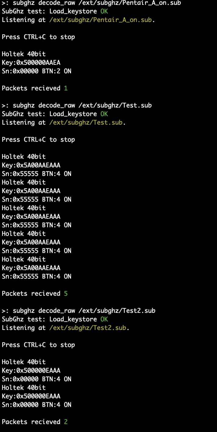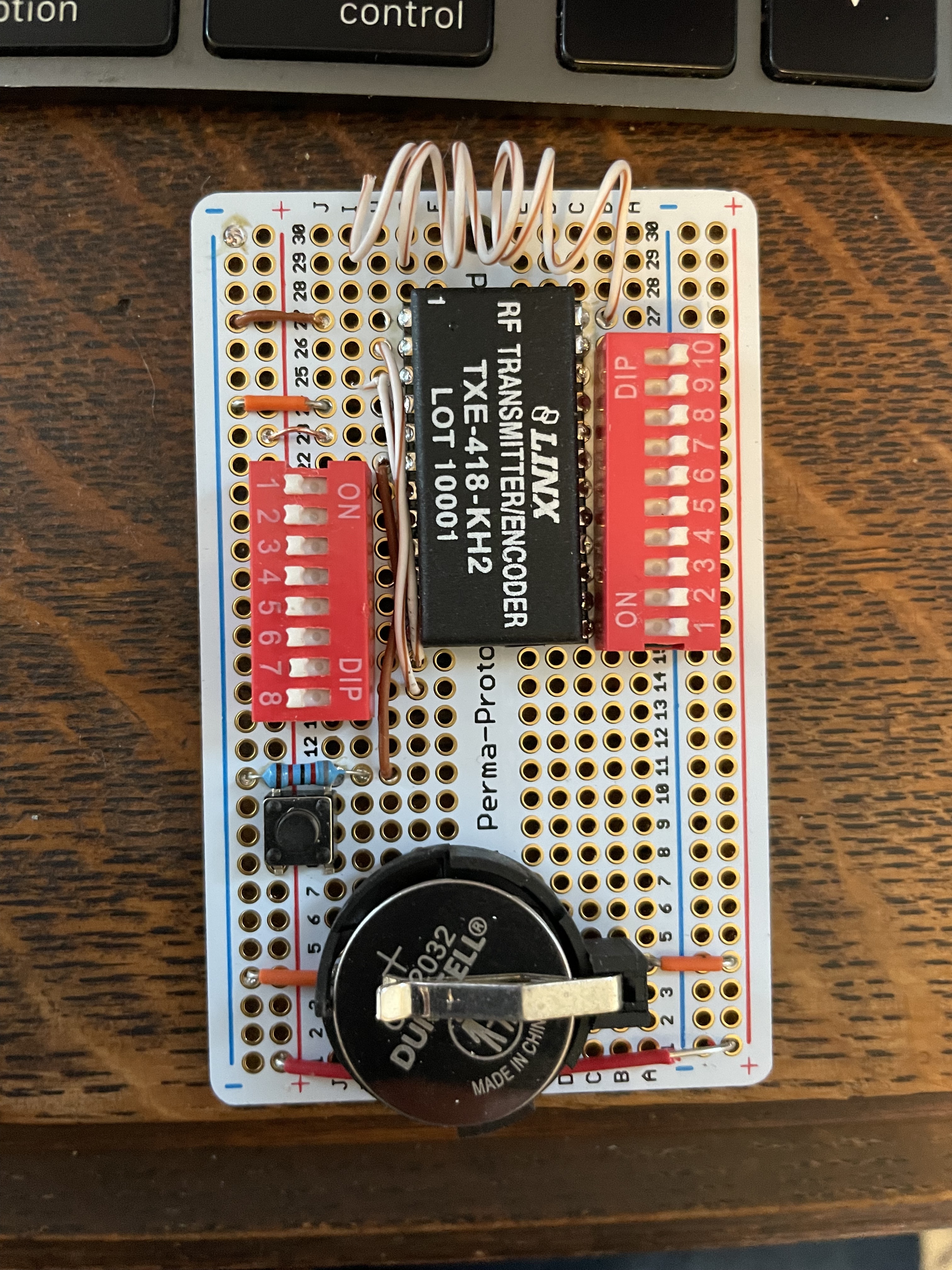
The Holtek encoding is also used in Linx remote products (and rebranded Pentair remotes for spas which are just Linx).
Multiple frequencies:
- 315 MHz
- 418 MHz
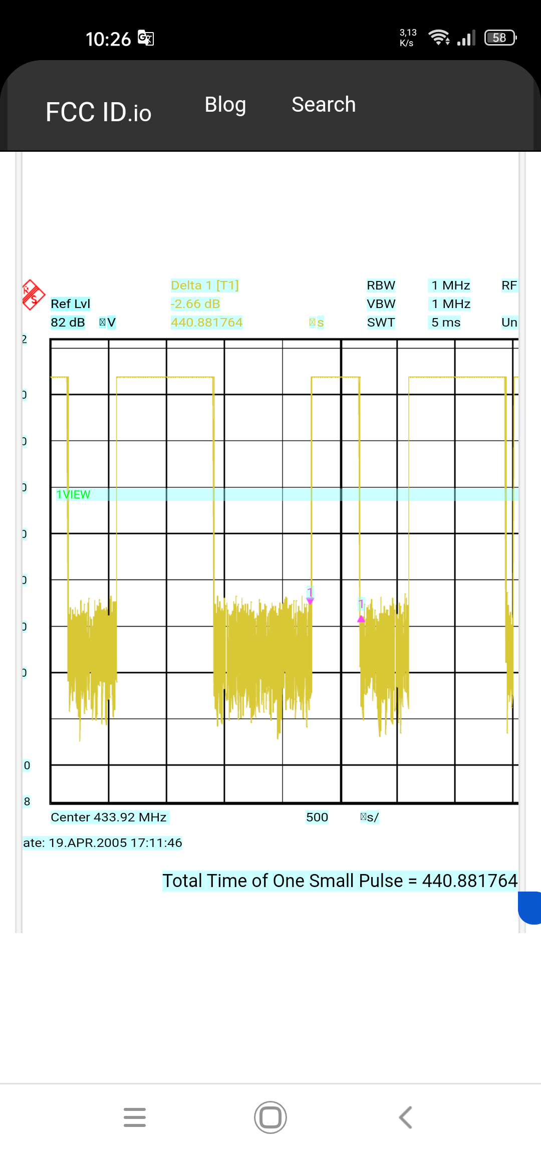
- 433.92 MHz
Modulation: ASK (OOK, AM)
Codes: static
https://fcc.io/OJM-CMD-HHLR-XXXA
Datasheet with protocol description: HT640 pdf, HT640 Description, HT640 Datasheet, HT640 view ::: ALLDATASHEET :::