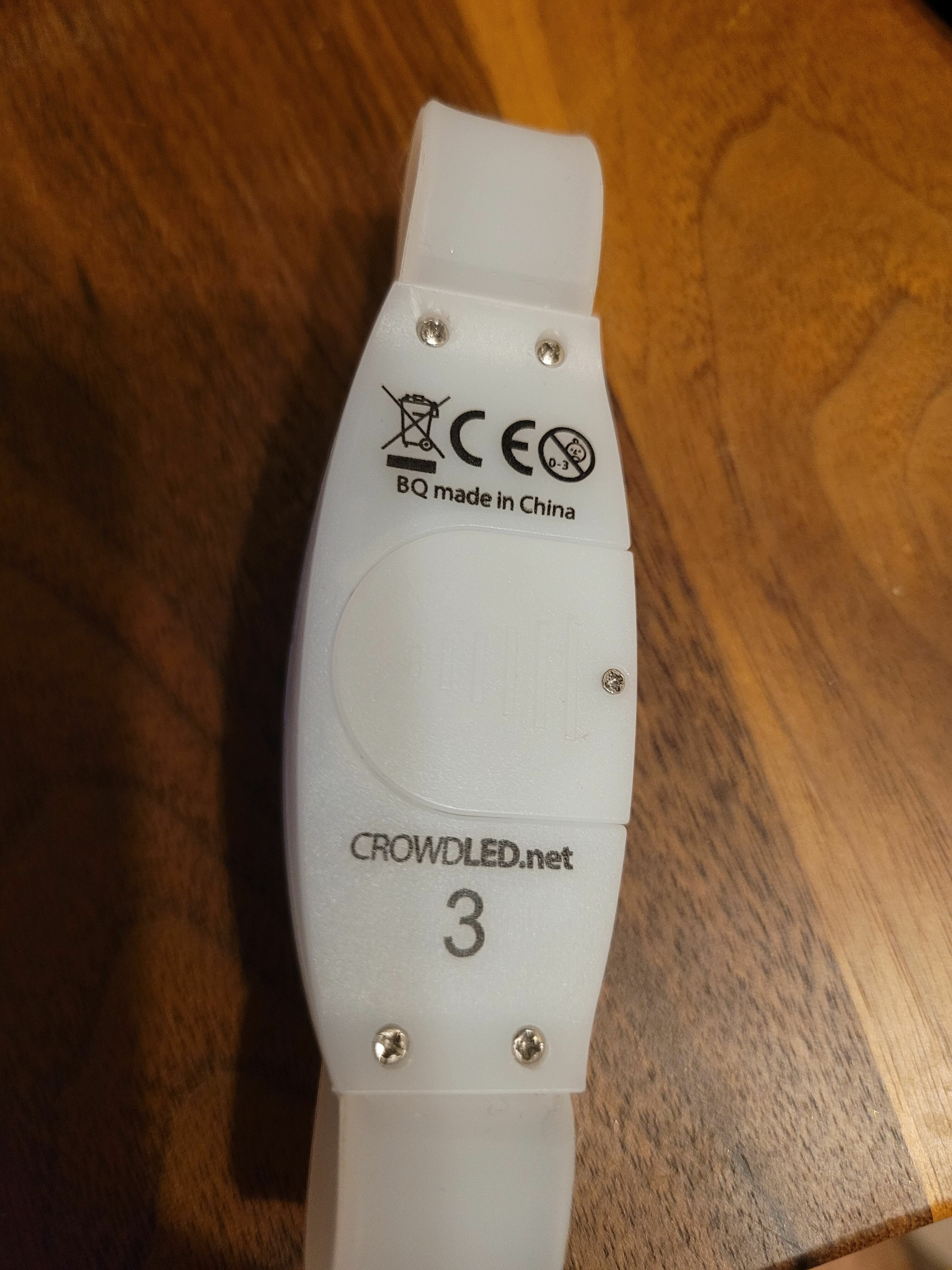
Got the device from https://crowdled.net/product/led-wristband/
Couldn’t capture frequency, but guess it’s 433.92 MHz
Chip inside - CMT2210LC
Protocol - DMX-512.

Got the device from https://crowdled.net/product/led-wristband/
Couldn’t capture frequency, but guess it’s 433.92 MHz
Chip inside - CMT2210LC
Protocol - DMX-512.
Guess is not good … Flipper team will not do anything with your guess … You need to provide working raw files if you want for a protocol to be added …
@onlinedevel The receiver frequency of the CMT2210LC is indeed 433 MHz. But any idea what the other IC on the PCB is? For some reason there is no ID on it. I guess it is some sort of LED driver or demultiplexer to drive the LED´s? I am looking for a similiar ic right now any suggestions?
I’ve gotten my hands on a few of these and managed to capture some raw dumps that turn the devices on/off and can put them in a mode that allows the user to press the button to pick their own colors.
The filenames can be deceptive, as I think in some of them I captured both a start and a stop broadcast at once.
Hopefully this is a good place to post them. I’ve tried using the web analyser but couldn’t find a way to filter out the signal from the noise - if anyone has tips on how to study these dumps, please let me know!
https://flpr.app/sf#path=subghz/CrowdLedStart.sub&key=YbCoI5_aLB80tzunZHo_9A&id=C8VNhc
https://flpr.app/sf#path=subghz/RAWstop.sub&key=RXD65Rc2jr6qHaqJ4ircyA&id=iUWM0L
https://flpr.app/sf#path=subghz/Stop.sub&key=lGcnB5UzXSihwZZWQFwCeQ&id=zO0696
hello @fantasy @onlinedevel
I have 2-3 of these bracelets but I dont have any flipper but some arduinos and some 433MHz modules.
Were you able to find the message/data/packets that needs to be send in order to control the bracelets ?
Thanks
Hej @fantasy
unfortunately your links have expired, could you maybe upload them again?
thank you very much
Hi, the download is broken. plz reupload the files
I already saw the message from @D0doooh yesterday. You saw that I replied 7 months ago, right? Calm the fuck down, I will upload it when I can.
@D0doooh , @Matthias_Muller … I have a backup of 2 files out of 3 ( I dont have RAWstop.sub ) and you can download those here 537.9 KB folder on MEGA
many thanks for uploading @diekaines
does it work for anyone? unfortunately my unit does not work, but I also don’t know if it is the right frequency (433 MHz) in Europe such things are often on 868 MHz.
or does the wristband have to be reseted somehow first?
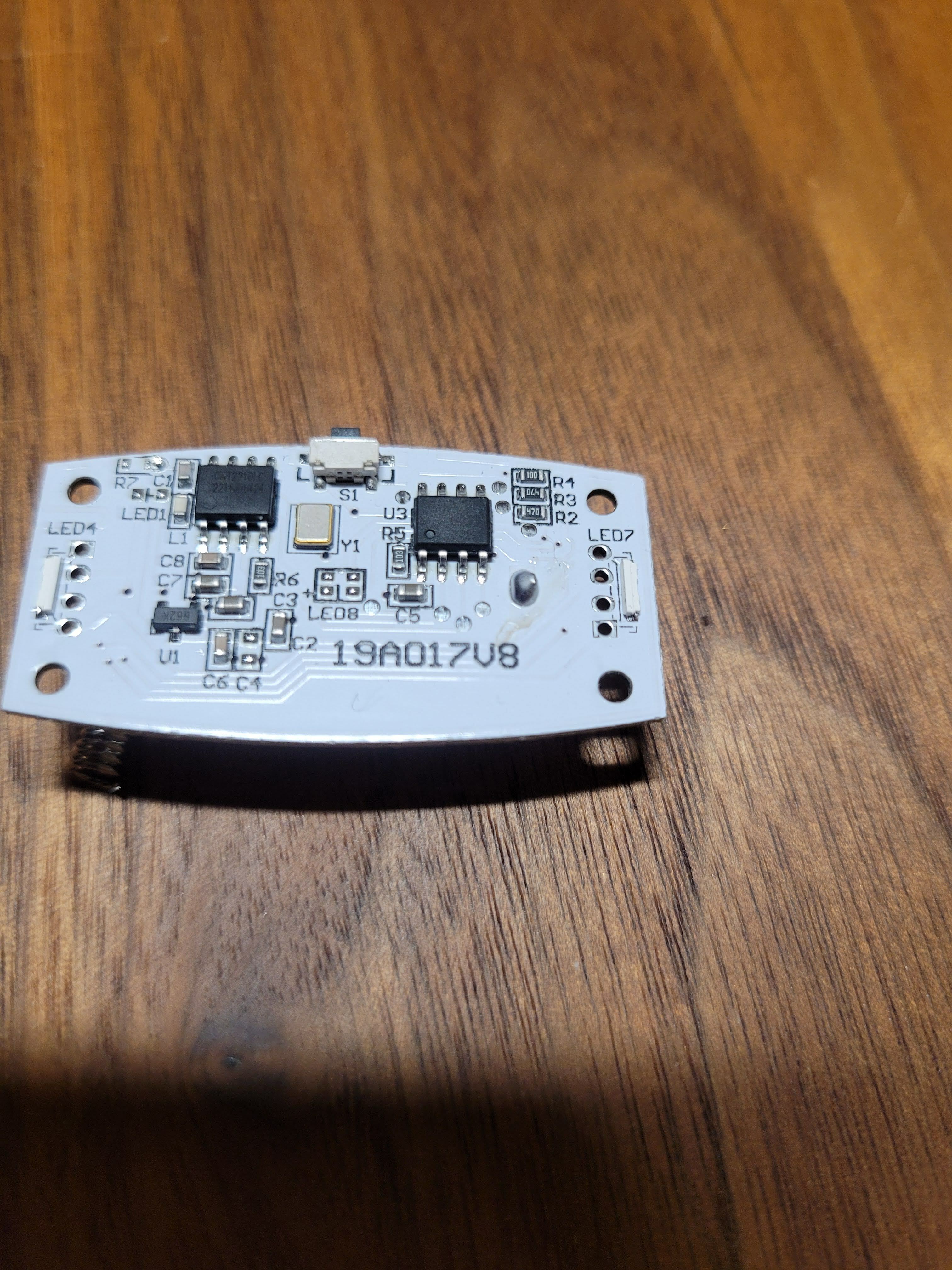
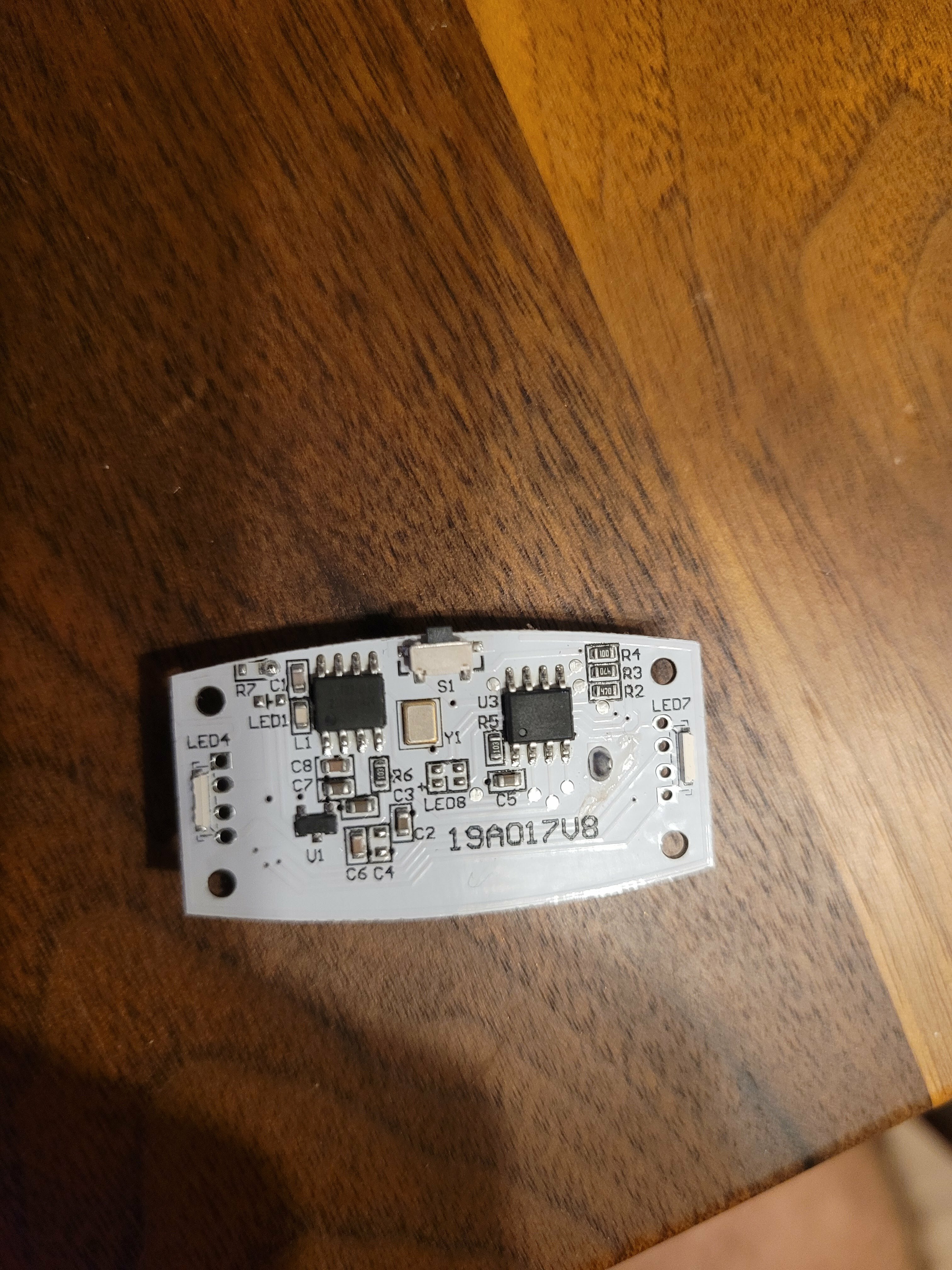
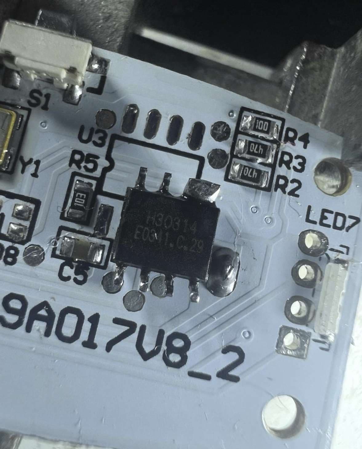
my board also has the following label: 19A017V8_2
Version 2?
Hi @D0doooh ,
I have the save “19A017V8_2” on my board and by looking at the pictures on the first post of this thread I dont see anything different. Even the missing ( not populated ) LED1 and LED8 and the hanging R6 is the same.
So i presume the changes are only software related to the IC chip on the right
Like @lleon said the first chip on the left is CMOSTEK CMT2210LC
https://datasheetspdf.com/pdf-file/1318988/CMOSTEK/CMT2210LCW/1 , which doesnt has any programming/flashing.
The frequency that chip/IC works is decided by the crystal/oscillator ( Y1 )
The device operates at either 315 MHz or 433.92 MHz through selecting a 19.7008 MHz or 27.1383 MHz
In other words that IC is pretty dump ( no programming needed) .
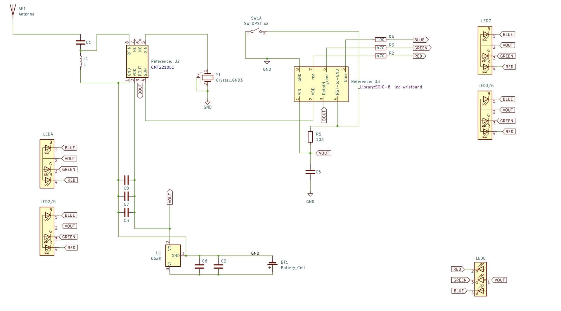
I desoldered both IC-s and the schematic is below . LED1 and LED8 on the board are unpopulated so I didnt put those on the schematic
The unknow chip/IC ( U3 on the right ) has marking on the bottom H30314 E0341.C.29 ( dont mind the two pins with solder bridge ) .
The voltage regulator ( U1 ) is marked 662K
https://www.lcsc.com/product-detail/Linear-Voltage-Regulators-LDO_Shenzhen-Fuman-Elec-662K_C841298.html
That has been also featured in a EEVblog video
https://www.youtube.com/watch?v=TdNUO3MSfJs
as the cheapest voltage regulator produced by Shenzhen Fuman Elec https://www.lcsc.com/brand-detail/932.html
The same company also makes MCU-s ( https://www.lcsc.com/products/Microcontroller-Units-MCUs-MPUs-SOCs_11329.html?brand=932 ) and there are 2-3 that has the same pin functionality ( VIN on pin1 , GND on pin8 , RESET on pin4 , pin5/6/7 PWM capable ) as the one on the wristband … so I presume the unknown IC is from them as well or maybe another of those cheap IC-s ( one time programmable ) as EEVBlog mentioned here https://www.youtube.com/watch?v=VYhAGnsnO7w
If thats the case ( cheap IC , one time programmable ) then the whole decoding happens on the IC via software.
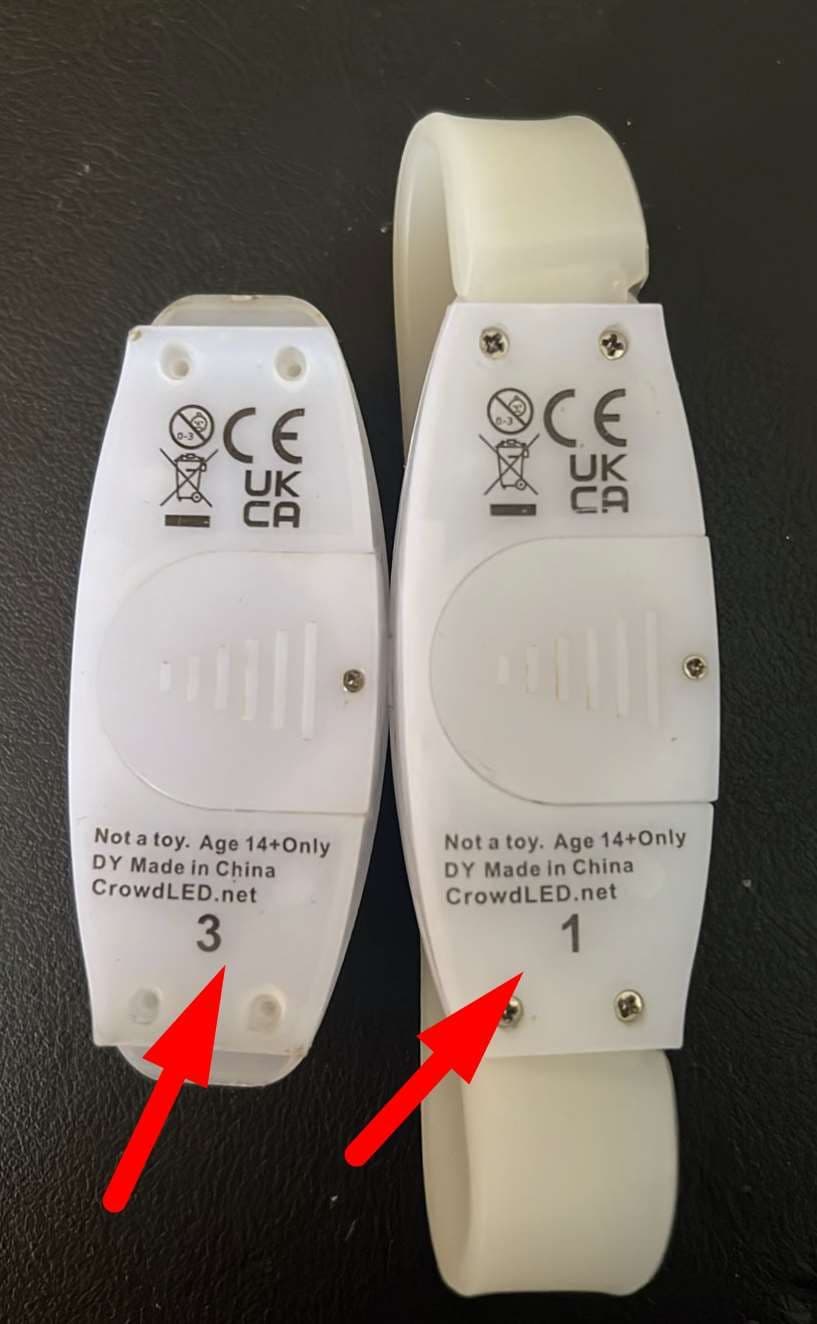
I have two wristband, one has a “3” and the other has “1” on the bottom .
This was the grouping so not all the wristband would light up but rather depending on the group. Both wristband has the same IC marking so the only thing left which would decide to which group the wristband belongs to would be the software that is programmed on the IC .
So the signal that the first IC receives , is sent to to pin3 of the unknown IC, which decodes the signal , checks if its for that group and lights up the led-s on pin 5/6/7 via PWM ( since i have seen the colors it emits are more than single red , green or blue )
Its also possible that the signal isnt “clear text”, I presume they have done some encryption/encoding or some padding
Maybe the best option would be to replace that unknown IC with any other known ( attiny , atmel , STI ) so you can have maybe a “433 detector” 
Anyway , that’s all I was able to find
Some interesting links
Programming the transmitter ( we have the receiver on the wristband ) maybe it might help decode the signal attached as files above by looking at what the transmitter of the same company is able to transmit
https://hoperf.com/uploads/AN1003-CMT2150A_CMT2210Acommunication_example(1527coding)_1695629742.pdf
Github repo
https://github.com/lupyuen/LoRaArduino/blob/master/libraries/HopeRFLib/HopeDuino_CMT211xA.cpp
Regards
PS: This forum doesnt allow me to post more that 4 links , so I had to make those as plain text, sorry
Hi @diekaines , I have used the files you uploaded. I have 5 CrowLED bracelets from group 3. I have managed to extract almost all the colors and some effects from the file you uploaded. Here are all the files for each color and effect. I hope you find it useful. PLEASE NOTE THAT IT WORKS ON GROUP 3 BRACELETS, I have not tested it with group 1 and 2 bracelets. I hope it works for you @D0doooh : https://github.com/niltefa/Flipper-Zero-CrowdLED-Wristbands
Take a look at the link I have posted, it might work for you if you have group 3 bracelets. @Matthias_Muller @onlinedevel
Hello @niltefa
Thanks for your work and the files
Would be great if you explain also how you were able to decode those files. I tried before myself with “universal radio hacker” and I saw the signals ( or at least what I think are the signals/codes ).
I also exported some of those as single ( from CrowdLedStart ) and since I don’t have a Flipper, I used a ESP32 to toggle a pin high/low and then connected that pin on ESP to the pin 3 of the unknown IC/chip but no success
The code I used on ESP is “Color Green” that you attached
#include <Arduino.h>
#define TRANSMIT_PIN D3

void transmit_raw(String raw_data);

String raw_data = "339 -198 359 -202 203 -194  .....";

void setup() {
  Serial.begin(9600);
  pinMode(TRANSMIT_PIN, OUTPUT);

  //  Get ready to transmit
  digitalWrite(TRANSMIT_PIN, LOW);
  delay(1000);
}

void loop() {
  transmit_raw(raw_data);

  delay(1000);
}

void transmit_raw(String raw_data) {
  int16_t time;
  bool value;
  unsigned int data_start = 0;
  unsigned int data_end = 0;

  // Converting String into char array
  char raw_data_array[raw_data.length() + 1];
  raw_data.toCharArray(raw_data_array, raw_data.length() + 1);

  //  Tokenizing and sending a bit at a time.
  char* token = strtok(raw_data_array, " ");
  while (token != NULL) {
    time = atoi(token);
    //  getting the high or low value of the bit.
    value = time > 0 ? HIGH : LOW;

    //  making time positive if it is not
    time = abs(time);

    //  sending a single bit and keeping it active for 'time' microseconds
    digitalWrite(TRANSMIT_PIN, value);
    delayMicroseconds(time);


    //  getting the next bit data.
    token = strtok(NULL, " ");
  }
}
I also tried one of those 433 Mhz transmitters https://www.aliexpress.com/item/1005001570442244.html but still no success ( with my code ) . Maybe because Im doing something wrong or since I have the “_2” board and the files captured are for the other board
Can you please let us know what board you have ? ( with or without the _2 )
Thanks once again for your work
Sorry @diekaines , I rectify. I have not used any of the files you have posted here, I have used the following file:
When I had the file I played it and realized that there were times when my bracelet started to light up and make effects.
When I played the whole file I wrote down all the colors and effects I had. Then I opened the file and did “brute force”. To do this:
I opened the file in Visual Studio Code and cut little by little the file until I had, for example, the red color, when I had it I saved the file and started again but looking for another effect or color. I have not really “analyzed” the file or anything like that. The only thing I have done was to remember little by little the file until I got the effect or color I wanted.
On the other hand, I disassembled one of the bracelets to see the components and I have exactly the same as you so in principle these files should work, the thing is that I understand that the .sub file does not work for the Arduino. I think that there are .py (python) scripts to change the .sub files to another format (check reddit).
Hi @niltefa
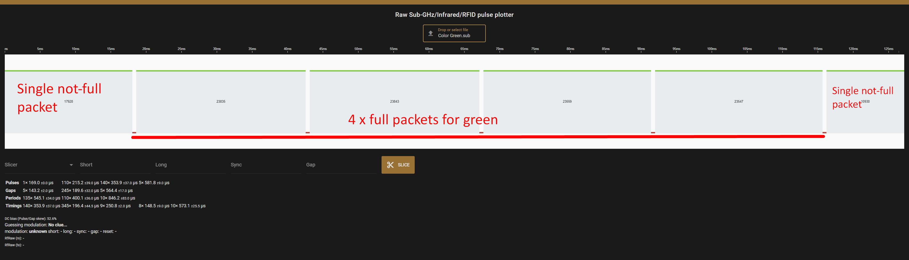
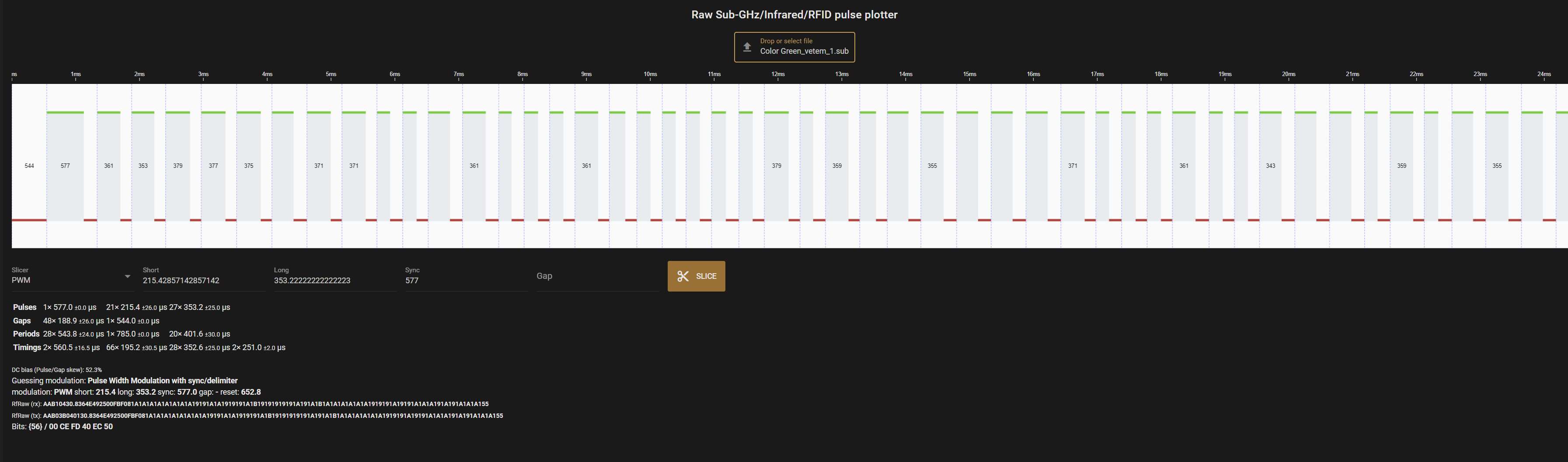
I took the green from your files and seems it has 6 repeating packets for the green. This makes sense since the receiver goes into sleep and thus the repeating is to make sure that it receives at least a packet ( between sleep/awken state ) . In the image below you can see the first corrupted(not full) packet of green , and then 4 full packets of green , and then another not-full ( corrupted ) packet
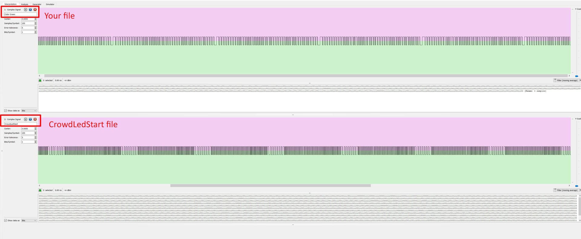
From that green file you uploaded , i extracted one of the full packet and its able to be decoded ( the text below the image shows the BITS)
Would it be too much to ask you to try playing that single file on flipper and see if that will turn on the wristband ? It might or might not work since its a single packet and the receiver needs to be awaken to receive/decode that.
Here the file
Thanks
@diekaines It does work. At some point, I had to press several times to get it to turn on. Video: 56.11 MB file on MEGA