GPIO Header with UART on a side of Flipper

It’s nice to have native instruments in multitool, but when your screwdriver not suitable — there is a chance that you can use knife blade.

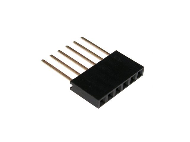
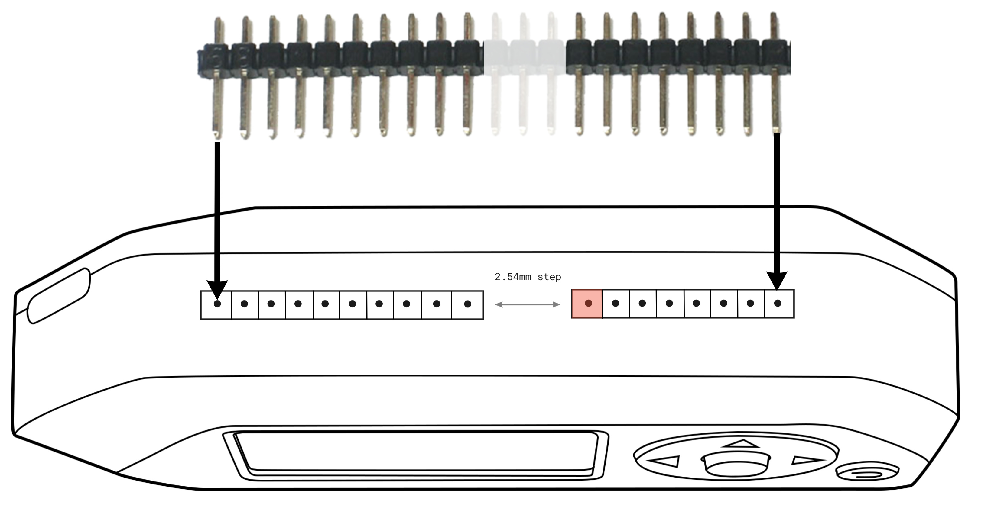
I think it’s nice idea to make unused raspberry gpio accessible through standart pin header on a side of Flipper.

ph50_1x6

2 Likes

What about logic level? Do we need TTL 5/3.3V levels or native RS-232 from -13 to +13V?

I believe TTL 5/3.3V would be the most universal.

In current renders there is single ground socket on the side of flipper. In real world you will need more than one ground and power socket if you won’t soldering every time. It’s not killer feature, but if there is some free space - you can fill it with useful sockets.

More one important thing - (one of?) 5v pin should be short connected to USB input. Then we will can build dock station and use external modules that need a lot of power (which cannot be shipped with internal step-up regulator)

Checkout new GPIO pinout. We also think about:

  • Make distance between holes groups multiple of 2.54mm so user can use single row of PLS connector
  • Add some key (closed pin hole?) to prevent incorrect positioning of module

1 Like

Wow, nice!

  1. Yep, I think it’d be easier to design boards with a single pins row
  2. What about two symmetrical closed holes, so the module won’t even partially fit if turned wrong side?
1 Like

What about the usual groove for a plastic plug? Why reinvent the wheel? Due to the difference in the pinout of some Chinese modules, I would have connected them via additional wiring anyway. And protection against incorrect installation is needed, as it seems to me, only for ready-made modules specially created for the flipper. And since they will be specially created, then a special pin can be added)

  1. yes, single connector
  2. yes, closed pin hole (different number of pins)

Aw, why you make pins on top of Flipper?

I think it’s good to place here two rows of pin holes with mirror pinout. In this case user can flip module and plug it in safely.

Too much

Nice that in new pinout two groups have different number of pins, so now it won’t be possible to insert some module the wrong side.

Having 2.54-compatible distance is nice in some cases, while not having it doesn’t seemingly give any bonus, so I think it should be multiple of 2.54

1 Like

Я думаю что шаг 2.54 очень правильная идея. Открывает много возможностей для майкеров

Ну что тут выдумывать, крадите идею у e-sata, на худой конец у ide штекера.
А вот шаг 2.54 это очень правильно

Добавить пару гаек внутри корпуса (можно стойки, но они будут выступать) по бокам GPIO линейки для фиксации модулей расширения винтами. Примерно как разъем VGA

Also i wonder if power and ground socket could have shallower depth than signal ones, so when inserting any device - power is getting connected first, avoiding overloading signal lines with suddent current shockwave.

If to talk SATA, etc, those have longer pins for power bus instea, but Flipper makers can not control add-on makers and force them to modify standard cheap pin arrays, so perhaps this should be better accomodated for inside Flipper